| title | Assembly & BOM |
|---|---|
| icon | hammer |
| description | Bill of Materials and assembly reference for building the Omi from components. |
The BOM contains 88 components across the mainboard, charger board, FPC, and mechanical assembly.
Download:
| Component | MPN | Manufacturer | Qty |
|---|---|---|---|
| Main SoC | nRF5340-CLAA | Nordic Semiconductor | 1 |
| Wi-Fi IC | nRF7002-CEAA-R7 | Nordic Semiconductor | 1 |
| Microphones | MMICT5838-00-012 | TDK | 2 |
| 8GB NAND Flash | CSNP4GCR01-DPW | CS | 1 |
| 6-axis IMU | LSM6DS3TR-C | STMicroelectronics | 1 |
| Battery Charger | BQ25101YFPR | Texas Instruments | 1 |
| DC-DC Buck | TPS628438YKAR | Texas Instruments | 1 |
| Load Switch | TPS22916CYFPR | Texas Instruments | 2 |
| RF Switch | FM8625H | FUMAN | 1 |
| LDO 3.3V | SGM2036S-3.3XXDH4G/TR | SGMICRO | 1 |
| LDO 1.8V | SGM2036S-1.8XXDH4G/TR | SGMICRO | 1 |
| Crystal 40MHz | CJ17-400001010B20 | CJ | 1 |
| Crystal 32MHz | 1S32000049 | Faith Long | 1 |
| Crystal 32.768KHz | DST1610A | KDS | 1 |
| Battery | GRP1654M1-1C-1S1P-3.7V-150mAh | GERUIPU | 1 |
| Vibration Motor | LBM0525A4123F | LIDEWEI | 1 |
| RGB LED | MHPA0606RGBDT | MEIHUA | 2 |
| Pogo Pins (device) | CA02-PG07 | JINLANTIAN | 6 |
| Pogo Pins (charger) | CA62-PG308 | JINLANTIAN | 2 |
| Tactile Button | TS-1001S | JINBEILI | 1 |
The mainboard uses 0201-size passives (resistors, capacitors) primarily from YAGEO and Murata. See the full BOM CSV for complete listings including designators.
**Sourcing tip for indie makers:** Order passives (0201 resistors/capacitors) from LCSC — they have the best prices and ship from China alongside your JLCPCB boards. For active ICs, Mouser/DigiKey have more reliable stock.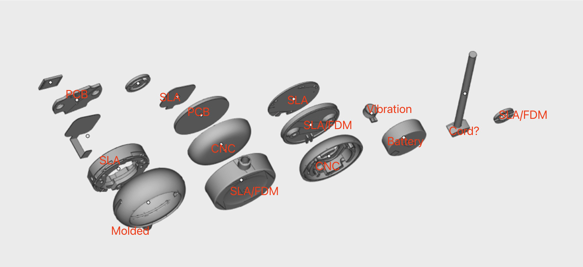
The device consists of these main assemblies:
- Front aluminium cover (CNC machined)
- LED light guide (SLA/translucent)
- Main frame (SLA/translucent PC+ABS)
- PCB mainboard with microphones, SoC, flash
- FPC connecting to charging contacts
- Battery (150mAh LiPo)
- Vibration motor
- Silicone pad
- Back aluminium cover (CNC machined)
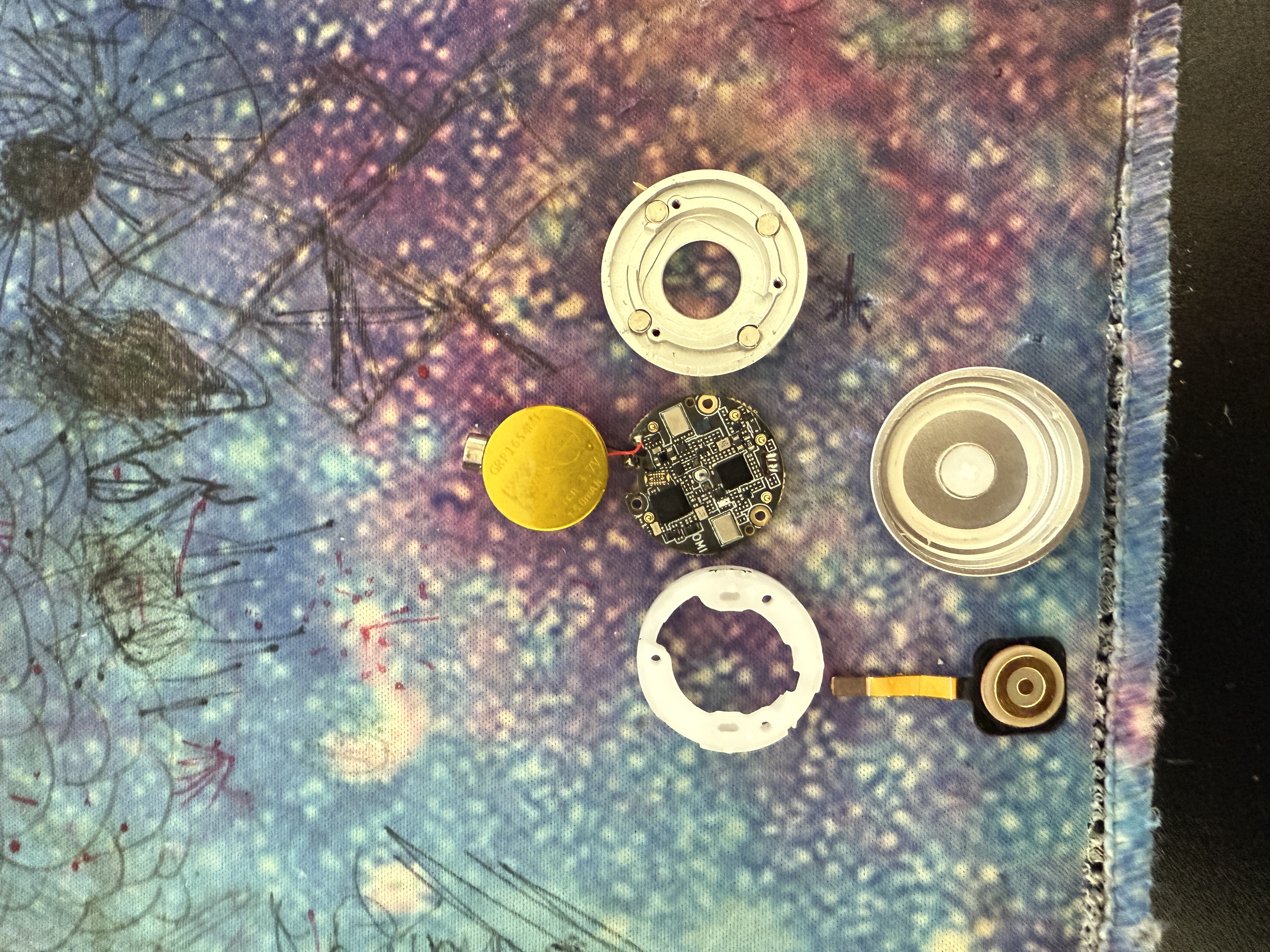
    Lay out all components on an anti-static mat. You'll need: tweezers, Phillips screwdriver (PH000), UV lamp, multimeter, and S300 adhesive.
  </Step>
  <Step title="Install PCB into frame">
    Place the mainboard PCB into the SLA frame on the mounting posts. Board should sit flat with no rocking. Connect the FPC cable to the board-to-board connector.

    <Warning>The FPC connector is fragile — lift the latch before inserting, then press down firmly to lock. Do not force it.</Warning>
  </Step>
  <Step title="Connect battery and motor">
    Plug in the 150mAh LiPo battery. Route the cable to avoid pinching. Attach the vibration motor with double-sided tape.

    <Warning>**Battery polarity is critical.** Reversed polarity will destroy the BQ25101 charger IC and may cause thermal runaway. Verify polarity with a multimeter before connecting.</Warning>
  </Step>
  <Step title="Install magnets and silicone pad">
    Apply UV adhesive to magnet seats. Insert 4x N52 magnets (D3×H3mm). Cure with UV lamp for 30 seconds each.

    <Warning>Test magnet polarity against the charger dock BEFORE gluing. Mark each magnet with a Sharpie. Once cured, they cannot be removed.</Warning>

    Place the silicone pad over the battery/motor assembly.
  </Step>
  <Step title="Close enclosure">
    Attach aluminium covers (Case A front, Case B back). Secure with 3x Phillips screws (CM1.2×5). Apply S300 glue around the seam.

    <Check>Before sealing: test charging contact continuity, verify BLE advertising, confirm both mics record audio.</Check>

    {/* WIP: Need a photo showing the actual enclosure-closing process (covers being mated, screws being inserted). @aarav */}
  </Step>
</Steps>
    <Check>All 6 checks must pass before packaging.</Check>
  </Step>
  <Step title="Package the device">
    Place device in foam insert, close the packaging case. The foam inserts protect the device during shipping.

    <Tip>Packaging STEP files are in [`packaging/cad/`](https://github.com/BasedHardware/omi/tree/main/omi/hardware/consumer/packaging/cad) if you want to manufacture custom retail packaging.</Tip>
  </Step>
</Steps>
Assembly photos are in assembly/photos/:
materials-labelled-exploded-view.jpg— All components identifiedmaterials-labelled.jpg— Materials and finish calloutscomponents-disassembled.jpg— Individual components laid outouter-aluminium-covers.jpg— CNC aluminium cover detail


| Part | Specification | Qty |
|---|---|---|
| Dust filter | 5.8x4.0x0.1mm | 2 |
| Double-sided tape (small) | D4xd1.5xH0.1mm | 2 |
| Double-sided tape (large) | 14x12.5x0.1mm | 1 |
| Phillips screws | CM1.2x5 | 3 |
| N52 magnets | D3xH3mm | 4 |
| Light pipe | PC, D6xH1.9mm (custom) | 1 |
| S300 glue | 20g/pcs | 1 |
| UV glue | DDY6203_6 | 1 |
| Necklace rope | 2.5mm, L650mm | 1 |
| Protection cover | 28.7x35.5x11mm (molded) | 1 |
All design files include SHA-256 checksums for verification against the original source files.
cd omi/hardware/consumer
sha256sum -c checksums.sha256